Copied & Translated from Kikan Fullerene
(April 2002) 5. Introduction of Laboratories
(38)
Shigeo Maruyama Group
Department of Mechanical Engineering, The
University of Tokyo
Updated: '02/5/3
Japanese Mode is Here
Contents
We are studying fullerene and nanotubes at
Department of Mechanical Engineering in Hongo
Campus of the University of Tokyo in Bunkyo-ku,
Tokyo [1]. Because of the recent boom of
nanotechnology and carbon nanotubes, we do
not need to spend too much time answering
the question "Why are you studying fullerene
and nanotubes at Department of Mechanical
Engineering?" I have described the detailed
explanation why and how I have started this
field of studies in more than 10 years ago,
after my 2 year visit to Professor Richard
Smalley at Rice University.
Here, we belong to Shoji-Maruyama Laboratory
in the department. Maruyama group was in
Engineering Research Institute of The University
of Tokyo for 3 years from 1998 through 2001,
and now it is back at Department of Mechanical
Engineering. The members of our group are
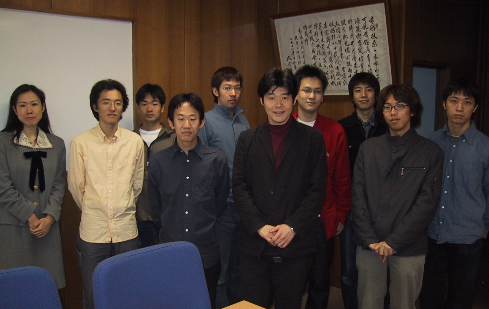
in Fig. 1. Three undergraduate students are
joining in end of April. The current research
topics of our group are all related with
single-walled carbon nanotubes; a half of
students is doing experiments and other half
is using molecular dynamics simulations.
[Click for enlargement]
Fig. 1. Group members in April 2002. From
left, Miwako Watanabe (secretary), Tatsuto
Kimura (PD), Shuhei Inoue (D3), Shohei Chiashi
(M2), Yasushi Shibuta (D2), Shigeo Maruyama
(Associate Professor), Kazunori Teshima (M2),
Satoru Ogawa (M1), Yuhei Miyauchi (M1), Yuki
Taniguchi (M1). Mitsuru Inoue (Research Associate)
is missing.
I have started research topics of fullerene
and carbon nanotubes after my 2 year visit
to Professor Rick E. Smalley at Rice University
from 1989. Initially, I studied carbon, silicon
and metal clusters with Fourier Transform
Ion Cyclotron Resonance (FT-ICR) mass spectrometer
[3,4]. At the time fullerene were called
as "clusters". After the discovery
of macroscopic generation technique of fullerene
by Kratschmer and Huffman, all members at
Smalley group started to generate fullerene
in arc-discharge technique [5].
After coming back to the University of Tokyo,
I have made the arc-discharge fullerene generator.
At the same time, I have started molecular
dynamics simulations of carbon cluster formation
process and others, partially because I could
not afford more experimental apparatus. When
I visited Smalley group for a month in 1992,
we have made a special carbon nanotube generator:
we tried to grow carbon nanotubes from a
tip of carbon fiber by focused Ar laser in
a vacuum chamber filled with a few Torr hydrocarbon.
At the time, the only detection technique
we planned was the expected field emission
from carbon nanotube. No SEM or TEM was there.
It took a few more years before they have
done interesting field emission experiments.
Probably, with current knowledge of nanotubes,
we can grow single-walled carbon nanotube
by tuning metal catalyst and carbon source.
I have changed my research topics from clusters,
fullerene, endohedral metallofullerene toward
carbon nanotubes: by constantly increasing
number of carbon atoms, in much slower pace
compared with Smalley group. My main interest
has been generation techniques and the self-assembly
generation mechanism [6-10]. I have generated
fullerene and SWNTs by using arc-discharge,
laser-oven, and catalytic CVD generators.
At the same time, precursor clusters were
examined with FT-ICR mass spectrometer with
direct-injection cluster beam source. Furthermore,
molecular dynamics method was used for simulations
of formation process of clusters, fullerene,
and SWNTs. Recently, several applications
of SWNTs were examined by molecular dynamics
simulations such as hydrogen storage and
heat conduction.
Research topics such as hydrogen storage
and heat conduction are very natural even
in Department of Mechanical Engineering and
I am very happy that I can talk about nanotubes
in conferences of my main field. Very recently,
many research activities related with carbon
nanotubes are actually being done in Mechanical
Engineering field.
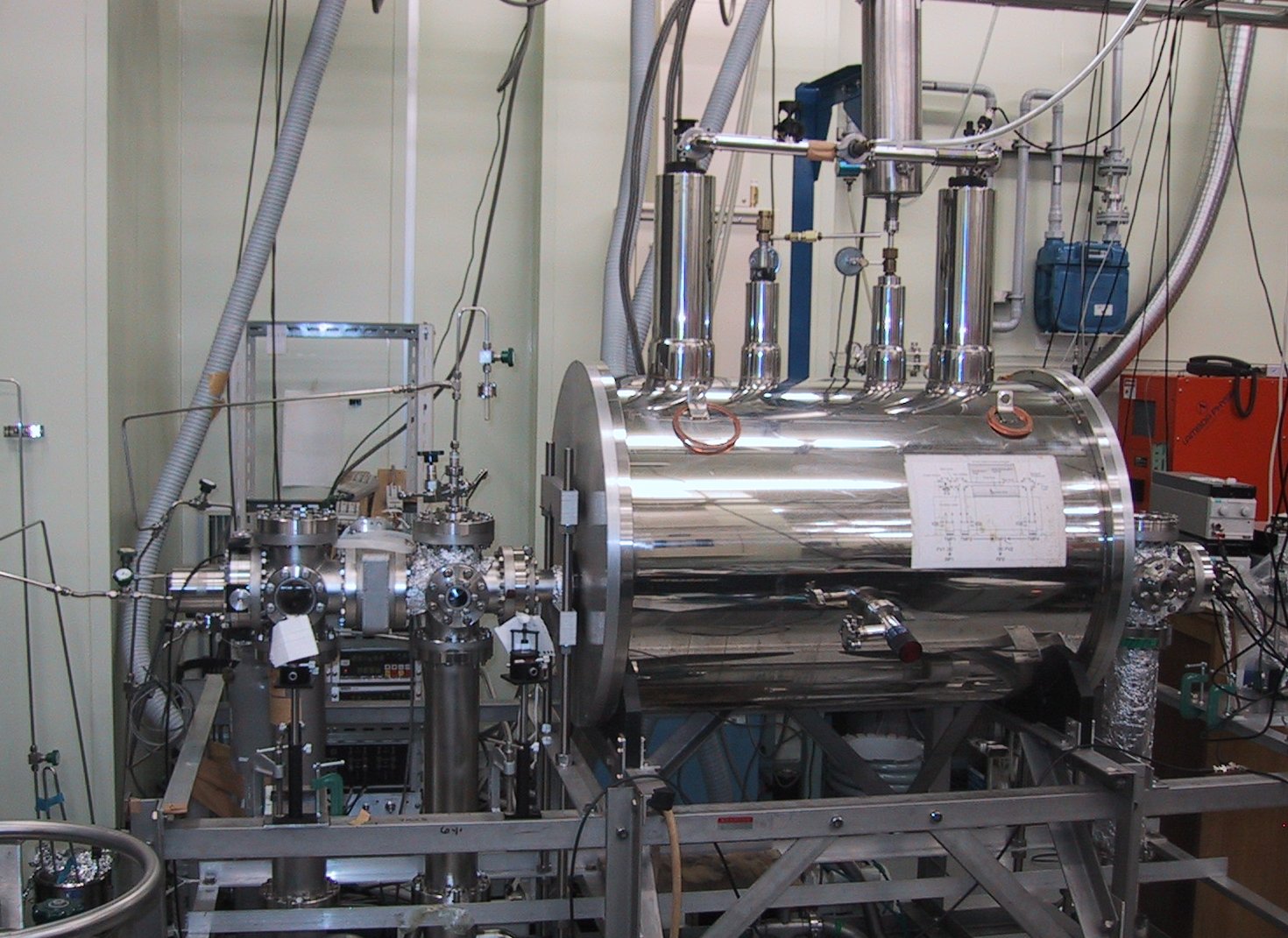
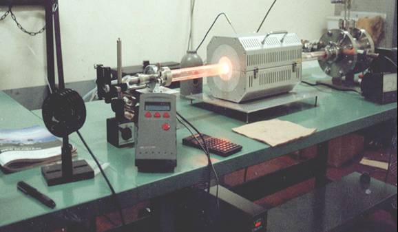
We have been working with the laser-oven
apparatus in Fig. 2, since the purest SWNTs
can be made with this technique. Dr. Masamichi
Kohno (previous research associate at Engineering
Research Institute, currently at AIST) designed
the apparatus based on the apparatus at Achiba
group at Tokyo Metropolitan University. He
was former PhD student of Professor Achiba.
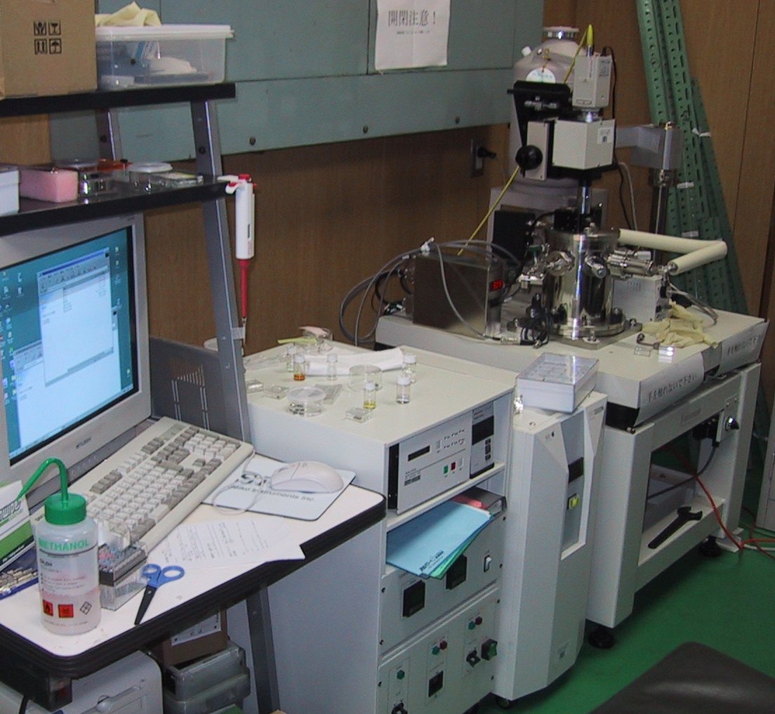
Since catalytic CCVD methods are recently
employed for quite pure generation of SWNTs
such as HiPco, we have converted the laser-oven
apparatus to the CCVD apparatus as in Fig.
3.
[Click for Picture]
Fig. 2 Laser-oven SWNT generator
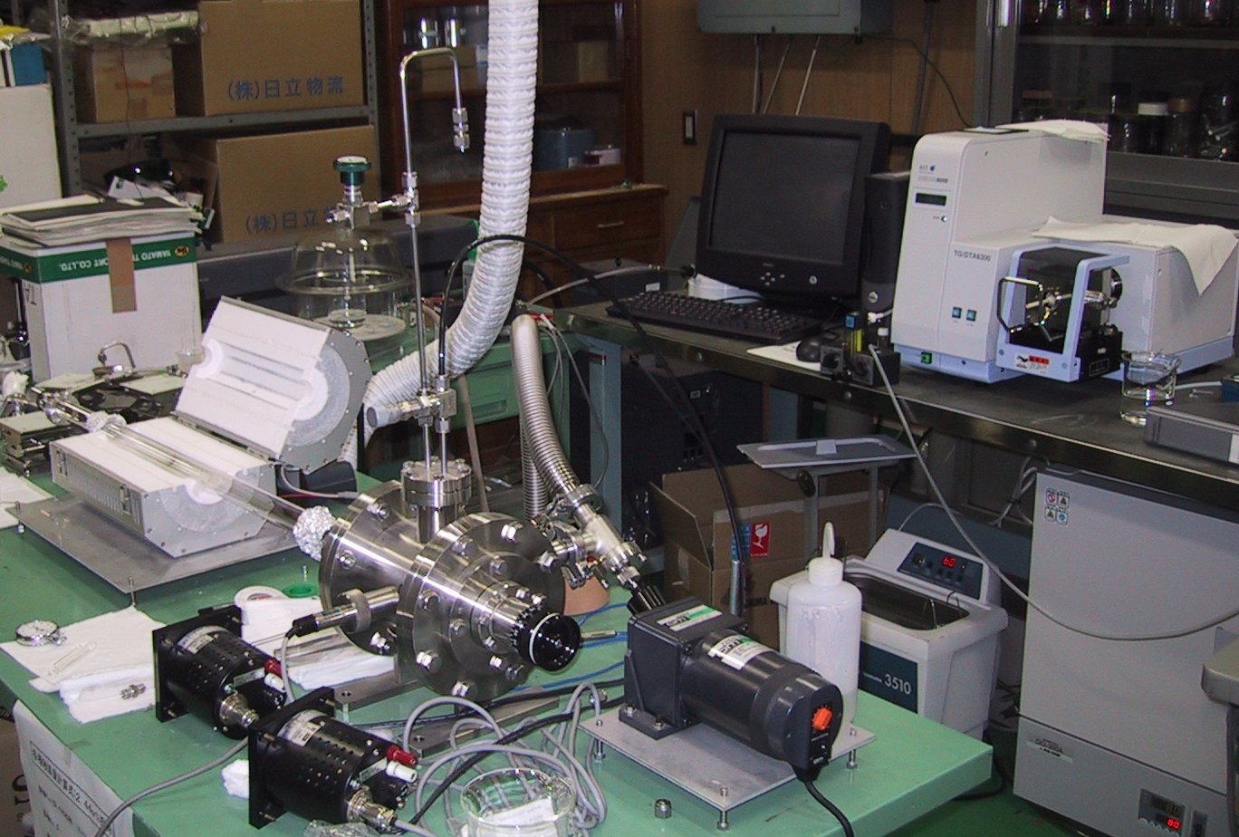
[Click for enlargement]
Fig. 3 Alcohol catalytic CVD apparatus
While we are trying the nanotube generation
from C60 as carbon source, we accidentally
found that very pure SWNTs were made from
ethanol used for the solvent of catalyst
metals [11]. Here, the Fe/Co metal catalysts
were supported with Y-type zeolite according
to the technique developed by Professor Shinohara
at Nagoya University. ' method. Our technique
is just very simple as follows.
(1) Catalyst on a quartz boat is set in the
quartz tube in the electric oven.
(2) While heating up the oven, Ar flow is
kept.
(3) At desired temperature, once evacuate
the quartz tube with the mechanical vacuum
pump.
(4) Introduce alcohol vapor flow from the
room temperature reservoir.
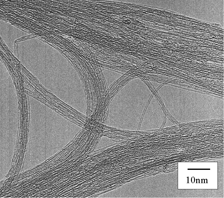
The TEM image of 'as grown' SWNTs at 800
deg. C reaction for 10 min. is shown in Fig.
4. No amorphous carbon, MWNTs, carbon nanoparticles,
metal particles are observed. Furthermore,
this alcohol CCVD method favors much lower
reaction temperature compared with normal
CCVD using hydrocarbons. Considerable amount
of SWNTs are made at 550 deg. C from methanol
[11].
[Click for enlargement][Click here for SEM picture]
Fig. 4 Transmission electron micrograph of SWNTs generated from alcohol CCVD method.
Raman spectra is now unavoidable technique
for SWNT characterization. The macro-Raman
apparatus in Fig. 5 was constructed in a
dark room just next to the CCVD apparatus.
Dr. Masamichi Kohno had mainly designed the
optics with kind advises from Professor Kataura
at Tokyo Metropolitan University. Ar ion
laser at 488 nm is used for the excitation.
After plasma-line filter, laser light is
mildly focus to the sample material, and
back-scattered light is introduced through
a notch-filter to 30 cm single monochrometer
(Chromex 500is2-0419) with CCD detector (Andor
DV401-FI).
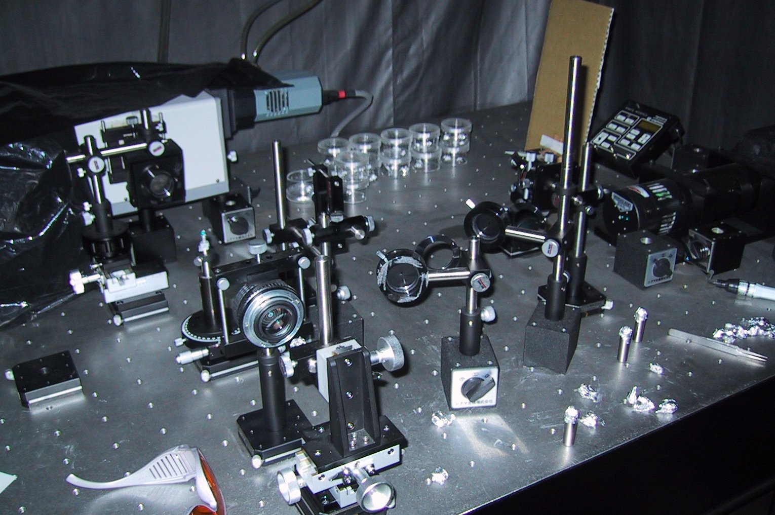
[Click for enlargement]
Fig. 5 Macro Raman spectroscopy apparatus
Fig. 6 compares Raman spectra of SWNTs generated
with Alcohol CCVD and with laser-oven method.
G-band (graphitic band) at around 1590cm-1,
broader D-band (disorder band) at around
1350cm-1, and RBM (radial breathing mode)
at 150Å`300 cm-1 are clearly observed for
both samples. Compared with the laser-oven
sample, diameter of SWNTs from ACCVD are
smaller and widely distributed. Because of
the thinner metallic nanotubes at around
240Å`300cm-1 excited with 488nm light, Breit-Wigner-Fano
(BWF) shape is observed for ACCVD sample.
It is well known that the observed Raman
of SWNTs is resonant Raman. The resonance
behavior depending on chiralities of nanotubes
are summarized as Kataura plot. Detailed
explanations and useful pictures for the
understanding and assignment of resonant
Raman scattering is shown in our home page
[12].

[Click here for temperature dependence of ethanol CCVD]
Fig. 6 Raman spectra of SWNTs from laser-oven
technique and alcohol CCVD techniques (Excitation
wavelength is 488nm).
We are using the TEM facility at Engineering
Research Institute and SEM apparatus at Nakao
Laboratory of our department. In addition
to these observations, we have implemented
the scanning probe microscopy (AFM/STM) as
shown in Fig. 7. This SPM by SII can be operated
with vacuum condition and special atmospheric
gas condition. It also have the temperature
control unit for -100 deg C through 800 deg.
C. In addition to the simple observation
of nanotubes, some handling experiments are
possible. Fig. 7 is an example of AFM image
of bundle of SWNTs which is prepared by laser-oven
method and purified with H2O2 solution.
[Click for enlargement]
Fig. 7 SPM (AFM/STM) apparatus with temperature
controlled vacuum chamber.
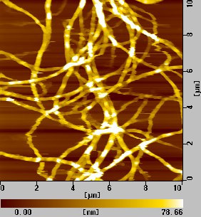
Fig. 8 An AFM image of purified SWNT bundle.
In order to study the formation mechanism
of SWNTs, generation experiments with laser-oven
and alcohol CCVD methods are not enough.
All we can observe are final results and
intermediate reactions process are only speculated.
Here, we use the FT-ICR apparatus with direct-injection
supersonic-expansion cluster beam source
for the detection of precursor clusters of
SWNTs [15-17]. Experiments are the same as
those for fullerene and endohedral metallofullerene
[13,14]. The simple difference is the kind
of metal atoms doped in graphite sample.
The basic design of our FT-ICR apparatus
in Fig. 9 is the same as Smalley group [4].
The experimental procedure is as follows.
(1) Solid sample is vaporized with focused
laser beam.
(2) With the timed pulsed He gas, clusters
are formed in the small nozzle and expands
to vacuum.
(3) Supersonically expanded and cooled cluster
beam is directly injected to the 6 T magnetic
field of superconductive magnet.
(4) Cluster ions are trapped in the ICR cell
for a minutes.
(5) Unwanted cluster ions can be excited
away from ICR by SWIFT technique.
(6) Chemical reaction and/or laser photo-dissociation
experiment can be done for trapped cluster
ions.
(7) High resolution mass spectrum can be
obtained from the ion-cyclotron resonance
frequency.
[Click for enlargement]
Fig. 9 FT-ICR mass spectrometer with direct-injection
laser-vaporization cluster beam source.
Fig. 10 is a mass spectrum of negative clusters
generated by laser-vaporization of Ni/Co
doped (0.6 at. %, each) graphite sample.
The bottom panel in Fig. 10 is the simulated
mass spectrum assuming the natural abundance
of isotopes of each elements. It should be
noticed that isotopes of H or C has almost
integer amount of mass in amu units. However,
with a metal atom such as Ni or Co, the deviation
from the integer mass due to the principle
of relativity are clearly observed. Some
of carbon clusters with about 50 to 55 carbon
atoms have a few Ni or Co atoms.
An example of chemical reaction experiment
with FT-ICR is shown in Fig. 11.
(a) As injected clusters.
(b) After 2 s reaction with NO at 10-7 Torr.
(c) After 10 s reaction with NO.
Carbon cluster ions with Ni or Co are very
reactive to NO. On the other hand, carbon
clusters with La, Y, Sc metal atom were quite
unreactive.
Fig. 10 Negative ion clusters from Ni/Co
loaded graphite sample.
Fig. 11 Chemical reaction of Ni- and Co-attached
carbon clusters with NO.
We have been studying the formation mechanism
of C60, the beautiful soccer ball structure,
with molecular dynamics method. Starting
from random gas-phase carbon atoms, the formation
process of C60 was reproduced. Base on those
simulations, we have proposed a fullerene
formation model [18,19]. Then, we have proposed
the classical potential function between
metal atoms (La, Sc and Ni) and carbon clusters.
Using these potential functions, formation
process of endohedral metallofullerene was
simulated [20-22].
The experimental conditions of generation
of SWNTs by arc-discharge and laser-oven
method are the same as for endohedral metallofullerene
except for the doped metals. Hence, the same
molecular dynamics simulation as for endohedral
metallofullerene is used for the SWNTs generation
by simply changing metal atom to Ni [23,24].
As an initial condition all atoms are in
random gas phase, and the growth process
of cluster are simulated. Ni-carbon binary
clusters with 50-100 atom range are shown
in Fig. 12. Most of carbon clusters seem
that they are trying to make spherical cage
structure, just like the cases of fullerene
simulations. However, one or two Ni atoms
are disturbing the complete closure. A metal
atom is always in the defect point (see the
animation).Those structures can explain the
results of FT-ICR experiments.
[Click for Annealing Animation of NiC60 Cluster]
Fig. 12 Molecular dynamics simulation of precursor cluster of SWNTs
A results of further collisions of those semi-spherical clusters is shown in Fig. 13. Since the very severe time-compression in the simulation, annealing of the structure is not enough. The simulation time is 4.5 ns after Fig. 12 but it corresponds to probably a few ms in the real experiment. Even though the structure shown in Fig. 13 is rather ugly, one can see that the tubular structure has grown longer by the collision and the coalescence. Ni atoms are slowly assembling to form Ni clusters, and they are diffusing around until finding the most stable position at the hemi-half-fullerene cap area.
[Click for Animation of Growth Process]
Fig. 13 An imperfect SWNT obtained from molecular
dynamics simulation
The high hydrogen storage capacity of carbon nanotubes has been reported for single-walled carbon nanotubes (SWNTs) and metal-doped graphite nanofibers. Because of its impact in applications in fuel cell vehicles, intensive experimental and theoretical works have been performed. Some of the most striking reports are questionable and theoretical models of physical adsorption cannot explain the hydrogen storage capacity of SWNTs more than 1 wt %. Current status of preparation of carbon nanotubes, hydrogen storage experiments, and theoretical works are being examined.
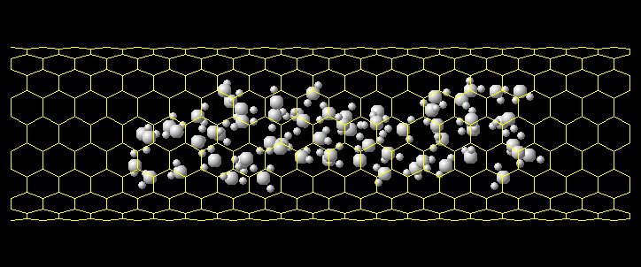
Here, we use molecular dynamics simulation
for the hydrogen physisorption with SWNTs
[25,26]ÅDFig. 14 shows the snapshot (Fig.
14(a)), potential energy distribution (Fig.
14(b)(c)) of a bundle of 7 (10,10) SWNTs.
Here, the temperature is 77K. Potential between
hydrogen-hydrogen, hydrogen-carbon, carbon-carbon
are expressed with Lennard-Jones (12-6) function.
For the bundle of (10,10) nanotube with diameter
1.36 nm, relatively strong absorption site
appears inside the tube (endohedral sites)
and between tubes (interstitial sites).Unfortunately,
the hydrogen storage capacity is lower than
1 wt % at room temperature [26]. However,
the absorption in the extremely small pore
of SWNTs are very exciting in general absorption
applications.
[Click for Animation of Phase Transformation]
Fig. 14 Molecular dynamics simulation of
hydrogen storage in a SWNT bundle [26].
The thermal conductivity of carbon nanotubes is speculated to be higher than any other material along the cylindrical axis. Hence, CNTs can be used as the superior heat conduction devices. In order to examine the thermal conductivity, we are performing molecular dynamics simulations[27-29]. Heat conduction of finite length single walled carbon nanotubes (SWNTs) is simulated by the molecular dynamics method with Tersoff-Brenner bond order potential. Temperature at each end of a SWNT was controlled by the phantom technique, and the thermal conductivity was calculated with Fourier's law from the measured temperature gradient and the energy budgets in phantom molecules. As shown in Fig. 15, the measured thermal conductivity at 300K did not converge to a finite value with increase in tube length up to 404 nm, but an interesting power law relation was observed. Probably the thermal conductivity will converge for much longer nanotubes. However, some electrical devices using SWNTs may not be much longer than 100 nm. Hence, the lower apparent thermal conductivity at the length scale must be very important. The diverging feature of thermal conductivity is discussed in the one-dimensional model cases [see 28,29].
Another purpose of this study is the preliminary connection of molecular dynamics techniques to the solid-state heat conduction usually discussed as 'phonon transport' in solid physics. In principle, the molecular dynamics simulation can be used to obtain information for phonon transport dynamics such as phonon dispersion relation, group velocity, mean free path, boundary scattering rate and the rate of phonon-phonon scattering (Umklapp process). Especially, the phonon scatting at an interface is very important issue in recent thin film technology.
The phonon density of states and photon dispersion relations are directly extracted from simulation results for further analysis of heat conduction mechanism based on the phonon concept. Fig. 16 shows calculated phonon dispersion relations and phonon density of states for (5,5) nanotube with 101 nm length. Phonon dispersion relation is obtained as the 2D Fourier transforms of deviation of each atoms from the equilibrium position. And, the phonon DOS can be calculated as the Fourier transforms of velocity fluctuations. Here, Fig. 16 (d) is the theoretical solution of the dynamical matrix by R. Saito at University of Electro-Communications.
[Click for Animation of Vibration of (10,10) Nanotube]
Fig. 15 Dependence of thermal conductivity of SWNT on tube length.
Fig. 16 Phonon dispersion relations and phonon density of states directly calculated from molecular dynamics.
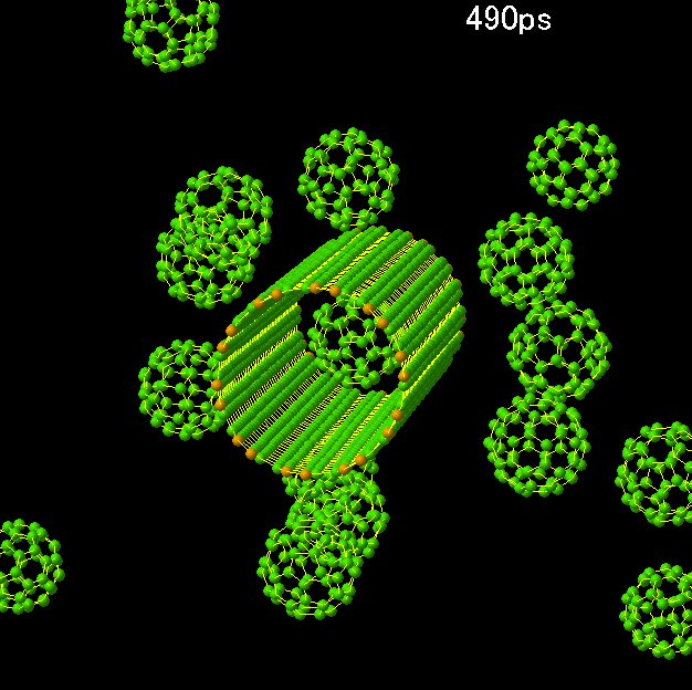
Several classical molecular dynamics simulations
related with carbon nanotubes are being performed.
They are physorption of hydrogen on SWNTs,
formation of peapod (Fig. 17), structure
of fullerene inside a SWNT, generation of
double walled-carbon nanotube from peapod,
bundle of SWNTs. For example, in the generation
process of DWNT from peapod, the fusion of
five C60 inside a (10,10) SWNT was simulated.
Depending on the simulation temperature,
the formation of polymers, peanuts type structure,
and DWNTs are simulated.
Fig. 18 shows the simulation of water cluster
insertion to a (10,10) SWNT. A larger water
cluster is bounced in the edge of SWNT but
a small cluster enters into a SWNT (see the
animation). We have been studying the condensation
process of argon liquid on a metal surface
[30] and structure of a water cluster on
platinum surface by molecular dynamics simulations
[31]. The wetting, phase-change, flow, heat
transfer of liquid inside the narrow SWNT
pore is extremely interesting from the theoretical
stand point. Furthermore, the nanoscale pore
of SWNTs is very fascinating in adsorption
technology.
[Click for Animation][Click here for Another Animation]
Fig. 17 Formation of peapod.
[Click for Animation]
Fig. 18 Water Cluster inside a (10,10) SWNT.
(1) http://www.photon.t.u-tokyo.ac.jp/~maruyama/nanotube-j.html.
(2) S. Maruyama, Kikan Fullerene, (1996), vol.
4, no. 4, pp. 106-113 (in Japanese).
(3) S. Maruyama, M. Y. Lee, R. E. Haufler, Y.
Chai and R. E. Smalley, Z. Phys. D, (1991),
vol. 19, pp. 409-412.
(4) S. Maruyama, L. R. Anderson and R. E. Smalley,
Rev. Sci. Instrum., (1990), vol. 61, no.
12, pp. 3686-3693.
(5) R. E. Haufler, Y. Chai, L. P. F. Chibante,
J. Conceicao, C. Jin, L.-S.Wang, S. Maruyama
and R. E. Smalley, Mat. Res. Soc. Symp. Proc.,
(1991), vol. 206, pp. 627-638.
(6) S. Maruyama, Kagaku-Kougaku, (1992), vol.
56, no. 6, pp. 422-423 (in Japanese).
(7) S. Maruyama, Kagaku, (1997), vol. 52, no.
5, pp. 20-22 (in Japanese).
(8) S. Maruyama, Kikan Kagaku Sousetsu, (1999),
vol. 43, pp. 10-19( in Japanese).
(9) S. Maruyama, Radiation Chemistry, (2002),
vol. 73, pp. 22-27 (in Japanese).
(10) S. Maruyama, Carbon Nanotube, Jyohou KikouÅC(2002),
pp. 103- 119 (in Japanese).
(11) S. Maruyama, R. Kojima, Y. Miyauchi, S. Chiashi
and M. Kohno, Chem. Phys. Lett., (2002),
submitted.
(12) http://www.photon.t.u-tokyo.ac.jp/~maruyama/kataura/kataura.html.
(13) S. Maruyama, M. Kohno and S. Inoue, Fullerene
2000: Chemistry and Physics of Fullerenes
and Carbon Nanomaterials, (2000), pp. 309-319.
(14) S. Maruyama, Y. Yamaguchi, M. Kohno and T.
Yoshida, Fullerene Sci. Tech., (1999), vol.
7, no. 4, pp. 621-639.
(15) S. Maruyama, Perspectives of Fullerene Nanotechnology,
(2002), pp. 131-142.
(16) M. Kohno, S. Inoue, R. Kojima, S. Chiashi
and S. Maruyama, Physica B, (2002), in press.
(17) M. Kohno, S. Inoue, A. Yabe and S. Maruyama,
Micro. Themophys. Eng., (2002), submitted.
(18) Y. Yamaguchi and S. Maruyama, Chem. Phys.
Lett., (1998), vol. 286, pp. 336-342.
(19) S. Maruyama and Y. Yamaguchi, Chem. Phys.
Lett., (1998), vol. 286, pp. 343-349.
(20) Y. Yamaguchi and S. Maruyama, Euro. Phys.
J. D, (1999), vol. 9, pp. 385-388.
(21) Y. Yamaguchi and S. Maruyama, Fullerenes:
Recent Advances in the Chemistry and Physics
of Fullerenes and Related Materials, (1999),
vol. 7, pp. 640-646.
(22) S. Maruyama, Endofullerenes: A New Family
of Carbon Clusters, (2002), in press.
(23) S. Maruyama and Y. Shibuta, Molecular Crystals
and Liquid Crystals, (2002), in press.
(24) Y. Shibuta and S. Maruyama, Physica B, (2002),
in press.
(25) S. Maruyama and T. Kimura, Proc. ASME Heat
Transfer Division 2000, Orlando, (2000),
vol. 2, pp. 405-409.
(26) S. Maruyama, Ohyo-Butsuri, (2002), vol. 71,
no. 3, pp. 323-326 (in Japanese).
(27) S. Maruyama, S.-H. Choi, Therm. Sci. Eng.,
(2001), vol. 9, no. 3, pp. 17-24.
(28) S. Maruyama, Physica B, (2002), in press.
(29) S. Maruyama, Micro. Themophys. Eng., (2002),
submitted.
(30) T. Kimura and S. Maruyama, Micro. Themophys.
Eng., (2002), vol. 6, no. 1, pp. 3-13.
(31) T. Kimura and S. Maruyama, Proc. 12th Int.
Heat Transfer Conf., (2002), in press.


![[Click here for SEM picture]](SEM.jpg)
![[Click here for Another Animation]](peapodshot.gif)